


|
1. Introduction of three-axis joint calibration drive shaft balancing machine
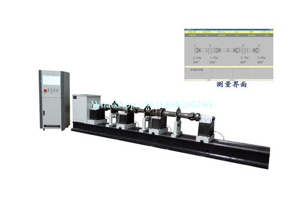
The three-axis joint calibration drive shaft balancing machine is a special balancing machine, which is specially used to balance the equipment of the automobile drive shaft, and only needs to replace the fixture of the installation workpiece to do the dynamic balance correction of various drive shafts. The equipment can not only carry out the joint correction of the three-section transmission shaft, but also the single-axis correction, and the joint correction of the two-section transmission shaft; The swing frame adopts a soft support structure, which is suitable for measuring the unbalance of the transmission shaft at a higher speed, and the measurement effect of the equipment is better.
2. Measuring system
★ Industrial control computer, 19-inch LCD monitor (touch screen can be configured according to customer needs), Windows operating platform
★ Equipped with the company's self-developed drive shaft balance special software, the software can choose single section, 2 sections, 3 sections of three types of drive shaft calibration; The operation is all based on the Chinese menu structure, and the text prompts of the operation steps
★ The measuring system is powerful: calibration, vibration signal display, and simultaneous display of unbalance on multiple calibration sides
★ The software comes with a permissible unbalance calculator, and the operator only needs to enter the allowable vibration accuracy level, mass, working speed, and radius of the workpiece to calculate the number of grams of allowable remaining unbalance of the workpiece
★ The software is completely developed in-house, and software functions can be modified or added according to customer requirements (e.g. scanning the QR code to add the identity name of the workpiece to the measurement results for future quality control)
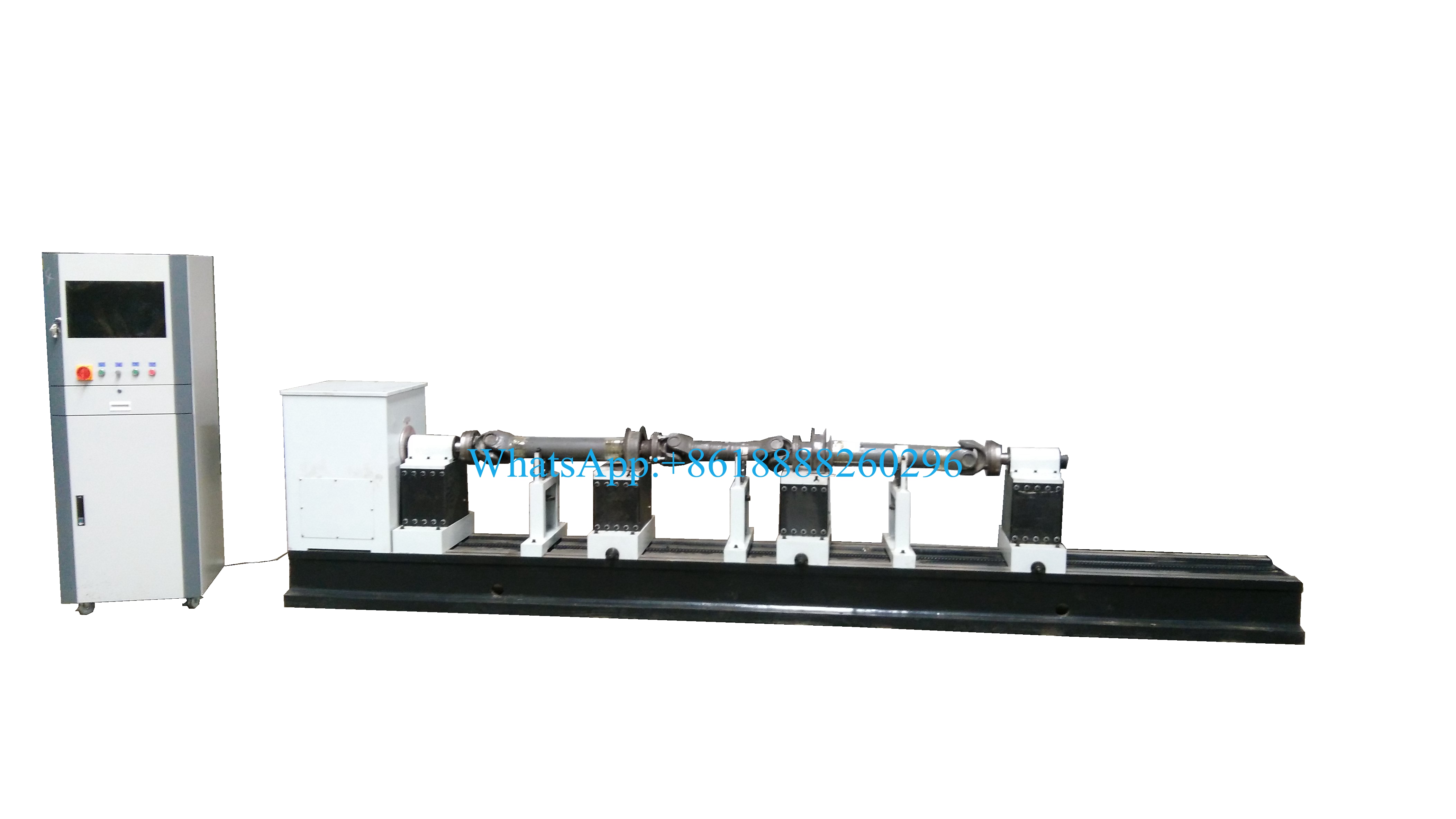
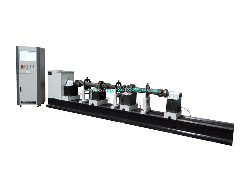
3. Mechanical part and control
★ The soft support swing and cast bed make the equipment more stable, and the unbalanced transmission shaft can be measured at a higher speed
★ The front and rear spindle structure of the balancing machine, in the middle are the two swing drivers that place the bridge. The front and rear spindle flanges are symmetrically slotted, and the general stop can be equipped with positioning rings of different sizes, so that the applicability of the equipment is stronger; When the three-axis joint school, the two spider plants in the middle of the transmission shaft are installed on the two bridge swing drives, and the middle bridge is installed on the left bridge swing when the two axes are connected to the school, and the middle swing is not used when the single section is calibrated
★ The swing frame can be moved along the bed and can be parked anywhere above the bed, so the machine can balance workpieces of any length within the effective length range given by the parameters.
★ Synchronous rotation scale marking is installed to facilitate the finding of unbalance angles.
★The speed measurement of the photoelectric sensor is suitable for high-speed measurement, and the vibration measurement of the magnetoelectric sensor is suitable for soft support structure
★ The frequency conversion speed regulation system is adopted, and the starting time of the equipment motor can be adjusted according to the need, which is convenient to use.
4. Technical Parameter
|
Model |
YDW-100A Ⅲ |
|
Weight of drive shaft(kg) |
≤100 |
|
Drive shaft correction method |
Single-section double-sided, two-section three-sided or three-section four-sided simultaneous correction |
|
Length of workpiece(mm) |
≤3000 |
|
Bed frame length(mm) |
4500 |
|
Balancing Speed(r/min) |
500-3000 |
|
Min. remaining unbalance |
≤20 gmm/kg |
|
Unbalance reduction rate (%) |
≥85% |
|
Motor Power |
3 KW |


