


|

1. Introduction of Drive Shaft Balancing Machine
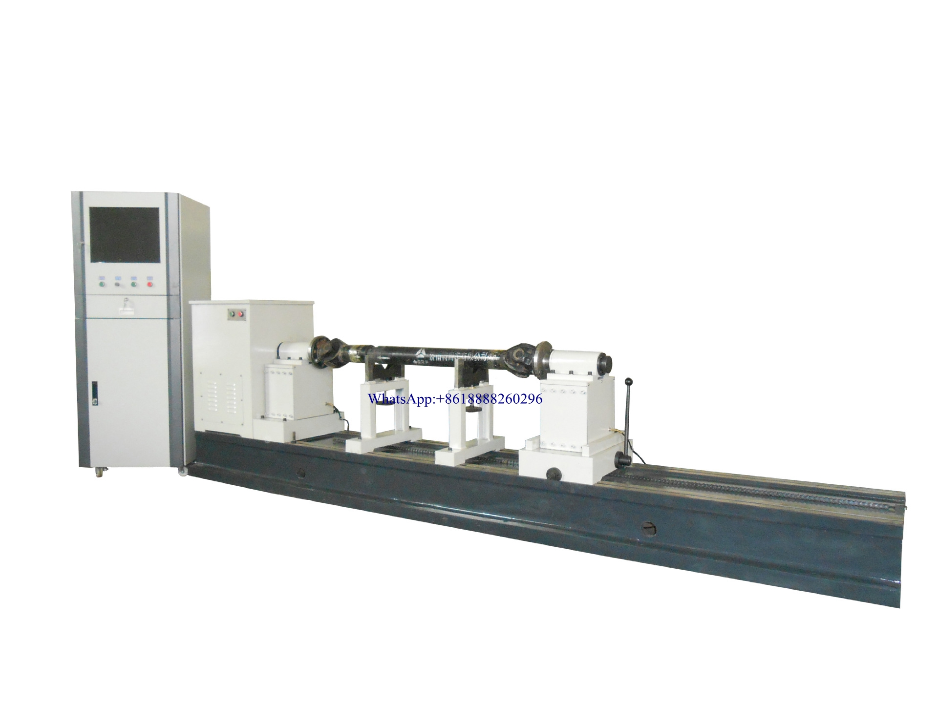
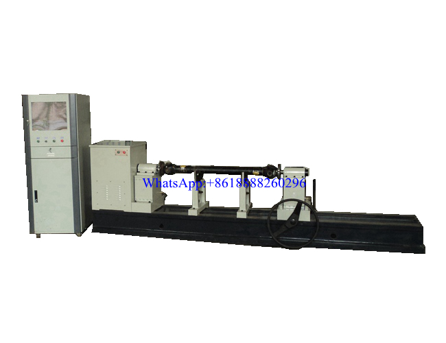
The transmission shaft balancing machine is a special balancing machine, which is an ideal device for balancing the transmission shaft of automobiles and other equipment. It only needs to replace the fixture to install the workpiece to do dynamic balance correction of various transmission shafts. The pendulum frame adopts a soft support structure, which is suitable for the measurement of the unbalance of the transmission shaft at a higher speed, and the measurement effect of the device is better.
2. Measuring system
(1) Industrial control computer, 19-inch LCD display, Windows operating platform
(2)Equipped with the company's independent development of a universal balance measurement system. The general software functions cover all the functions of the domestic mainstream balancing machine software, the operation adopts the Chinese menu structure, and the operation steps text prompts
(3) Powerful measurement system performance: Any workpiece calibration, wide measurement speed range 80 rpm start measurement, measurement speed block, unbalanced amplitude and phase stability, high deduplication rate and separation ratio, high sensitivity
(4) The software has a permissible unbalance calculator. The operator only needs to enter the permissible vibration accuracy level, quality, working speed, and radius of the workpiece and click to calculate to get the grams of the remaining unbalance of the workpiece.
(5) The software is completely developed independently, and the software function can be modified or added according to customer requirements (for example, scan the QR code to add the workpiece identity name to the measurement result and save it)
3. Mechanical parts and controls
(1) Soft support swing and casting bed, the equipment is more stable, and the unbalance of the transmission shaft can be measured at a higher speed
(2) The structure of the front and back spindles of the balancing machine, the flange has symmetrical long grooves, and the universal stop can be equipped with positioning rings of different sizes, which makes the equipment more applicable
(3) The pendulum can move along the bed and can stop at any part above the bed, so the equipment can balance workpieces of any length within the effective length range given by the parameters.
(4) Install the synchronous rotating scale mark, which is convenient for finding the angle of unbalance.
(5) The photoelectric sensor is suitable for high-speed measurement of speed, and the magnetoelectric sensor is suitable for soft support structure when measuring vibration
(6) Adopt frequency conversion speed regulation system, adjust the starting time of the equipment motor according to the needs.
4.Technical Parameter
|
Model |
YDW-100A |
|
Weight of drive shaft(kg) |
≤100 |
|
Drive shaft correction method |
Single-section double-sided correction |
|
Length of workpiece(mm) |
≤2100 |
|
Bed frame length(mm) |
3500 |
|
Balancing Speed(r/min) |
500-3000 |
|
Min. remaining unbalance |
≤5gmm/kg |
|
Unbalance reduction rate (%) |
≥85% |
|
Motor Power |
2.2KW |


