Taian AEM Machinery Co.,Ltd
Tel:+86 18888260296
Whatsapp:+86 18888260296

News
Machine Tool Spindle Balancing
Machine Tool Spindle Balancing
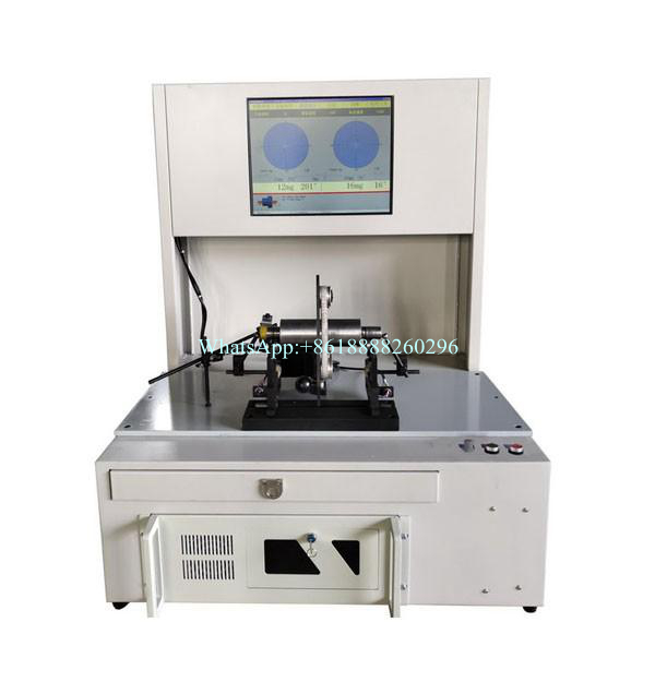
The spindle is the heart of CNC machining centers, milling machines, lathes, and high-speed industrial machinery. Because machine tool spindles operate at exceptionally high speeds and demand micron-level accuracy, dynamic balancing is critical to achieving mirror-like surface finishes on workpieces and preventing premature wear on high-precision spindle bearings.
1. Key Challenges in Spindle Balancing
1) Extreme RPMs & Micro-Precision: Modern motorized spindles (built-in motors) and high-speed mechanical spindles often operate from 10,000\text{ RPM} to well over 30,000\text{ RPM} (and up to 60,000+{ RPM} for specialized PCB drilling or engraving spindles). At these speeds, even a fraction of a gram-millimeter of unbalance causes severe vibration.
2) Surface Finish Degradation ("Chatter"): Unbalance in the spindle transmits directly through the tool holder to the cutting edge, resulting in visible chatter marks, poor surface roughness, and reduced tool life.
3) Bearing and Taper Wear**: High centrifugal loads degrade high-precision ceramic or hybrid bearings and can distort the internal taper (e.g., BT, HSK, or CAT tapers), compromising tool changing accuracy.
2. Balancing Approach: Component vs. Complete Spindle
Spindle balancing typically requires a two-pronged approach:
A. Component-Level Balancing (Pre-Assembly)
The Parts: Individual components such as the spindle shaft, internal sleeves, pulleys, and locking nuts must be balanced independently before assembly.
Recommended Machine**: High-sensitivity **Horizontal Belt-Drive Machines (YYQ Series)** or specialized vertical balancing rigs. Belt-drive is preferred here to ensure zero drive-induced runout or surface scratching on precision-ground journals.
B. Complete Motorized / Integrated Spindle Assembly Balancing
The Assembly: Once the bearings, rotor, and shaft are assembled into the housing, final dynamic balancing is performed.
How It Works: Specialized balancing cradles or customized fixtures hold the assembled spindle. The machine measures unbalance at the operational bearing journals, guiding the technician to correct the balance via fine-balancing screws or precision material removal on dedicated balancing rings.
3. Correction Methods
1) Precision Balancing Screws / Plugs: Many high-speed spindle designs incorporate threaded holes on the spindle nose or balancing ring where tiny mass-adjustment screws can be added or removed.
2) Material Removal (Milling/Grinding): Controlled, micro-milling on designated balancing webs or non-functional surfaces of the internal rotor or shaft collars.
3) Tool Holder Balancing (Complementary Step): In CNC machining, the balance of the spindle is only as good as the tool holder inserted into it. Tool assemblies (tool holder + collet + cutting tool) must also be dynamically balanced on dedicated tool balancing units.
【 Go Back 】 | 【 Print 】 | 【 Close this window 】
Contact us
ADD: No.96,Changcheng Road,Tai'an City,Shandong Province,China
Official Social Media


